Underwater Robot Platform for Feedback Control
Spring/Fall 2019
This is my MSR final project, advised by Dr. Mitra Hartmann, Hannah Emnett, and Kevin Kleczka. The project was driven by a need for an underwater robotic platform for the ongoing research conducted by Dr. Hartmann and her group. The goal was to be able to send custom messages/data from the robot to the tethered computer, and the computer be able to control the robot.

Since her group did not have a suitable robot, the first task was to explore commercially available underwater robots and purchase one. I looked into a variety of options, from remote-controlled underwater drones to educational robot kits, each with its advantages and disadvantages. The former would work out of the box, but were not easily modifiable, both in hardware and software. The latter could be 'built' to our needs, but that would also require a lot of time and effort.
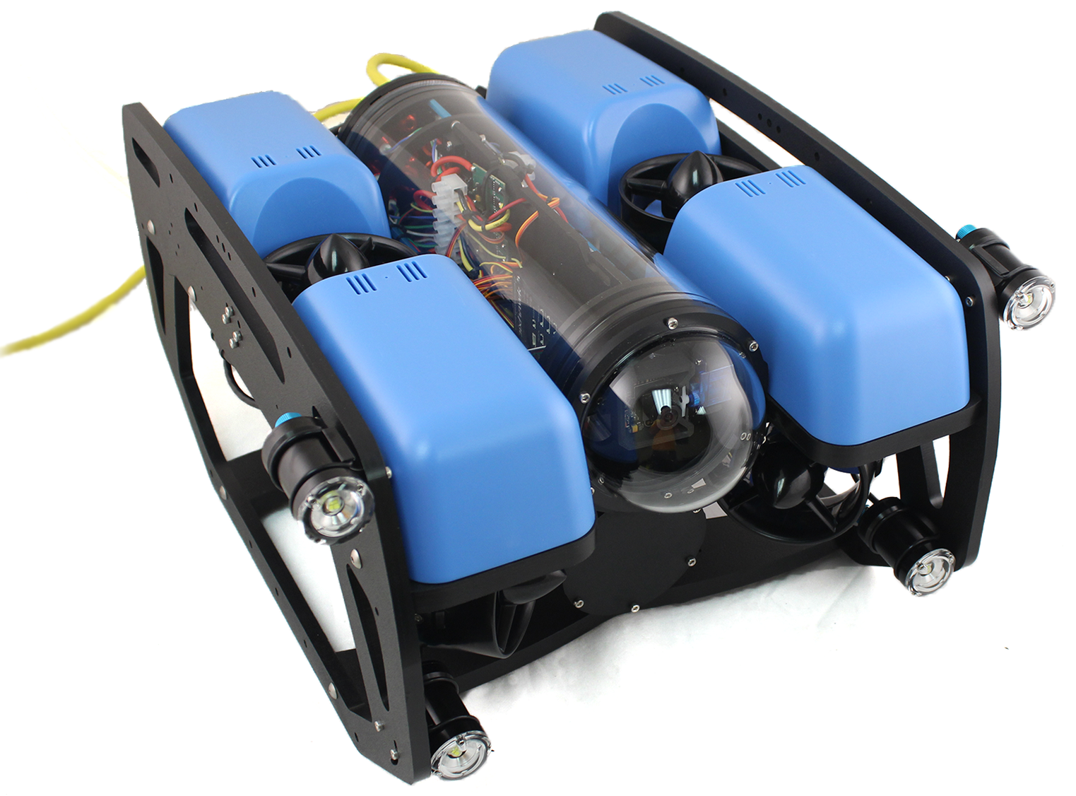
Ultimately, we settled on the BlueRobotics BlueROV2 shown on the left, a nice compromise between a kit and a finished, commercial product. Although the robot came unassembled, all of the individual components were already made and tested, meaning that the user only had to put the pieces together, which also only took about seven hours - compared to the double digits required for the aforementioned kits. Much of the hardware, electronics, and software was open source, with anything proprietary being heavily documented online. In addition, all of this was easily accessible and somewhat receptive to further modification (BlueRobotics sells additional sensors and accessories, obviously with instructions on how to integrate them, but anything custom is up to the user.)
Image from BlueRobotics
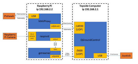
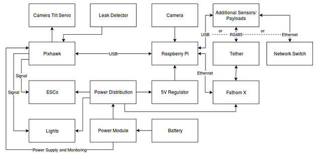
As previously mentioned, the software and electronics on the BlueROV2 is open source. Specifically, the autopilot software is ArduSub, a derivative of the widespread ArduPilot software used on aerial drones, run on a Pixhawk autopilot board. The Pixhawk is also connected to a Raspberry Pi 3, which acts as a companion computer, a device that receives vehicle data from the autopilot for further use, usually on some sort of ground control station (GCS) software. This data is then transmitted through the robot's tether to a topside computer, which then displays this data via QGroundControl, a GCS software. The software stack and a generalized hardware flowchart are shown below.
Software and Hardware diagram from ArduSub documentation
To send custom messages (such as data from custom sensors wired to the Pi) from the Pi to the tethered computer, I wrote two python scripts, one running on the Pi and the other on the topside computer. Intially, I tried to use the mavlink protocol over UDP, which is how the robot streams telemetry to QGroundControl. However messaging with mavlink only worked on the same port as QGroundControl, which meant that the scripts were also picking up on all the other telemetry data, which was very unnecessary for the scope of this functionality. Therefore, I switched to using python's built-in socket module, which used TCP, and this worked flawlessly. Oddly enough, the socket implementation only worked if the Pi ran as the server and the topside computer as the client.

For controlling the robot with commands from the topside computer, I used bluerov_ros_playground, an unofficial ROS package created by one of BlueRobotics' own engineers. From pretty early on, we were set on using ROS; Dr. Hartmann's students and I were all familiar with it and there was a good chance that other BlueROV2 owners - perhaps other researchers - had made their own packages for the robot. In fact, BlueRobotics had created an official ROS package for the BlueROV, the predecessor to the current robot. Unfortunately, they had not seriously updated the package in years.

With this package, I was able to successfully control the robot by publishing UInt16 values to the set_pwm topics for the various rc channels. Each of these channels were responsible for a different motion for the robot, i.e. rc_channel2 for roll, rc_channel5 for forward/backward, and rc_channel6 for later side-to-side motion. What this is essentially doing is mimicking the values that the autopilot would otherwise receive from joysticks on a physical controller, with each rc_channel representing an axis on the joysticks. The gif below demonstrates the robot moving in rectangular path, implemented as a series of publishes to topics run via rosnode.